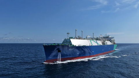
After nearly 20 years of accumulation, China Classification Society (CCS) has established the service capacity of liquefied gas carriers, and comprehensively formed the standard system of liquefied gas carriers, including the supporting software and service products. Up to now, there are 80 CCS-classed large liquefied gas carriers (orders inclusive), and the classed ship types cover large membrane-type LNG carriers (NO96 and MARK containment systems), large A-type independent tank LPG carriers (VLGC), B-type independent tank LNG carriers, large ethane carriers (VLEC), C-type independent tank LNG carriers, etc .

After nearly 20 years of accumulation, China
Classification Society (CCS) has established the service capacity of liquefied
gas carriers, and comprehensively formed the standard system of liquefied gas
carriers, including the supporting software and service products. Up to now,
there are 80 CCS-classed large liquefied gas carriers (orders inclusive), and
the classed ship types cover large membrane-type LNG carriers (NO96 and MARK
containment systems), large A-type independent tank LPG carriers (VLGC), B-type
independent tank LNG carriers, large ethane carriers (VLEC), C-type independent tank LNG
carriers, etc .
This paper will focus on the main technical
points of LNG carriers, and the achievements of CCS in the key technologies of
various types of LNG carriers (membrane, A-type, B-type and C-type) in recent
years, such as hull structure, liquid cargo containment system, sloshing
analysis, fatigue strength assessment, application of new materials, risk
assessment and industry organization requirements .

Figure 1 Type of CCS-classed Liquefied Gas Carriers
Technical Key
Points of Various LNG Carriers
1. Membrane-type LNG carrier
The membrane-type liquid cargo tank used in
membrane-type LNG carriers is non-self-supported, which needs to be in closing
contact with the hull and supported by the hull structure. Due to the unique
flatness laying requirements of the containment system of the membrane tank,
full protection to the cryogenic liquid cargo and deformation control of the
containment system, the hull in the cargo tank area is constructed as a
complete double-hull structure with double-layer bottom, double side,
double-layer deck and double-layer transverse bulkhead. All adjacent supporting
members (including longitudinal skeleton, stiffeners and main support
structures) of the liquid cargo tank are all arranged at the double-layer
bottom, double hull, convex deck and double-layer transverse bulkhead facing
outside the liquid cargo tank.

Figure 2: Hull Structure of Cargo Tank Area of
Membrane-type Liquefied Gas Carrier
(Left) and Membrane Containment System (Right)

Figure 3 Direct Calculation of Structure in Membrane-type
Liquefied Gas Tank Area

Figure 4 Joint between Double-layer Transverse Bulkhead and
Double-layer Bottom Longitudinal Truss

Figure 5 Joint between Vertical Truss and Deck Longitudinal
Truss of Double-layer Transverse Bulkhead

Figure 6 Joint between Horizontal Truss and Transverse
Bulkhead between Double Hulls
At present, the rules and technical standards
of CCS’s membrane-type LNG carriers have fully covered: the general
longitudinal strength requirements, standard
dimension requirements, direct calculation of cargo tank area structure,
direct calculation of whole ship structure, fatigue strength evaluation,
spectral analysis based fatigue strength evaluation, strength evaluation under
sloshing load, pump tower vibration and temperature field analysis
requirements. CCS has the service capability for single classing the
membrane-type LNG carriers.
Deformation
Control of Containment System
In addition to the typical key nodes of
traditional liquid cargo carriers, such as the upper/lower folding angle of
bottom side tank, the lower folding angle of top side tank, and the
intersection of large elbow plate of double-hull horizontal longitudinal truss
and bulkhead, membrane-type LNG carrier also includes the high stress parts
such as the joint between the double-layer transverse bulkhead vertical truss
and the double-layer bottom longitudinal truss, the joint between the
double-layer transverse bulkhead vertical truss and the deck longitudinal
truss, and the joint between the horizontal truss and transverse bulkhead
between double hulls. These parts are similar to the T-shaped intersection
joints. In order to keep the area facing the inner side of liquid cargo tank
smooth, these T-shaped intersection joints must be strengthened by inserting
local thickening plates to reduce the stress level and prolong the fatigue
life. At the initial stage of design, it is necessary to design these T-shaped
intersections reasonably to control the relative deformation.

Figure 7 Load Distribution of Sloshing Non-impact Motion and
Sloshing Impact Motion
Sloshing
Analysis of Containment System
For a long time, sloshing load prediction and
structural response is one of the technical challenges in the design of LNG
cargo tank containment system. CCS’s Guidelines for Evaluation of Sloshing Load
and Component Dimension of Liquid Tank (referred to as the Sloshing Guidelines)
classifies the sloshing motion into horizontal Class I, horizontal Class II and
horizontal Class III according to the intensity from low to high based on the
sloshing resonance of the ship and liquid cargo tank, among which horizontal
Class III includes the impact motion, and corresponding loads are given
respectively.

Figure 8 Structural Strength Evaluation of Pump Tower and
Accessories
For small liquid tanks with high resonance and
large liquid tanks with low resonance, the Sloshing Guidelines gives the hull
structure check requirements under non-impact sloshing load by standard
formulas. For large liquid tanks with high resonance, the Sloshing Guidelines
stipulates that the load shall be calculated directly for sloshing impact load,
and the results of sloshing model test can be used as sloshing design load
after approval . The Sloshing Guidelines adopts the method of "equivalent
static load", introduces dynamic amplification factor, transforms the
sloshing impact load of liquid cargo tank into the equivalent static load directly
acting on the hull structure, and properly considers the "buffer
effect" of the containment system. For the loading and unloading equipment
of the membrane LNG tank containment system - pump tower and its accessory
structure, the Sloshing Guidelines clarifies the content and process of
structural strength evaluation of pump tower, providing guidance for the
structural design and plan approval of pump tower in the industry.
Fatigue
Strength Assessment (Hull Structure + Cargo Containment System)
The LNG carriers generally have a service life
of 40~45 years, and the fatigue strength assessment of key parts in cargo tank
area is also the focus of attention in the design stage of membrane LNG
carrier. CCS’s Guidelines for Fatigue Strength of Hull Structure (referred to
as Fatigue Guidelines) specifies the fatigue strength assessment requirements
for membrane LNG carrier and other parts based on equivalent design wave load
system. Among them, the folding angle area under the bottom side tank and the
joint between the double-layer bottom longitudinal truss and the double- layer
transverse bulkhead are particularly important.

Figure 9-1 Upper and Lower Folding Angles of Inclined Plate
in Bottom Side Tank Figure
9-2 Joint between Double-layer Bottom Longitudinal Truss and Double-layer
Transverse Bulkhead

Figure 9-3 Joint between Double- hull Horizontal Truss and
Transverse Bulkhead
Figure 9-4 Joint between Liquid/Air Chamber Opening and
Convex Deck

Figure 10 Convex Deck Rear End Elbow Plate and Deckhouse
Opening

Figure 11 Fatigue Strength Check Position of NO96 Membrane
Containment System
Based on the principle of direct load
prediction and fatigue spectrum analysis, CCS issued the Guidelines for Fatigue
Strength Assessment of Hull Structures based on Spectral Analysis , and gave a
"personalized" fatigue strength analysis solution suitable for
membrane LNG carriers on specific routes. Besides the key nodes in the cargo
tank area, the evaluation sites further include the toe end of the elbow plate
at the rear end of the convex deck in the bow and tail areas of the ship, and
the entrance and exit corners above the deckhouse side walls connected with the
longitudinal walls participating in the total longitudinal strength.
In addition to the hull structure, the fatigue
strength evaluation of cargo containment system shall be paid attention to in
the design process of membrane LNG carrier. According to the Rules for
Construction and Equipment of Ships Carrying Liquefied Gases in Bulk (referred
to as Bulk Liquid Rules), CCS has formulated the "Guidance Document for
Plan Approval of NO96 Membrane- type Cargo Containment System". According to the Miner
linear cumulative damage criterion and North Atlantic environmental conditions,
this document stipulates that the stress distribution obeys the rules of
Weibull distribution, with the excess probability of 10~8, and the fatigue life
criterion of joints is 40 years. The loading conditions considered include full
load, ballast, complete cooling (considering 20 years, once a year) and partial
cooling. The loads include hull girder load and temperature load. The
evaluation positions include: the joint between the invar anchoring flat steel
and the top of transverse bulkhead; the joint between the invar pipe and the
lower end of the transverse bulkhead; the joint between the second layer lap
lath of invar steel and the lower end of the transverse bulkhead; the
reinforced joint of liquid cargo tank at trihedron of inner bottom plate,
transverse bulkhead and the inclined plate of bottom side tank. Different joint
forms shall be evaluated by different SN curves.
2. A/B-type LNG carrier
The A-type independent liquid cargo tank used
by A-type liquefied gas carrier is self-supported, with complete secondary
panel. A-type liquefied gas carriers are divided into super-large fully cooled
VLGC carriers suitable for loading liquefied petroleum gas (LPG) with a minimum
temperature not lower than -55℃, and LNT A-BOX LNG carriers suitable for loading liquefied
natural gas (LNG) with a design temperature of -163℃. B-type
liquefied gas carrier is similar to A-type liquefied gas carrier. But B-type
independent liquid cargo tank can adopt some secondary panels, which shall be
checked by model test and fine calculation, such as crack propagation and
leakage analysis of liquid cargo tank based on fracture mechanics. Some of its
secondary panel shall meet the protection requirements of liquid cargo leakage
at sea for at least 15 days, and shall still make the secondary panel fulfill
its functional requirements at the static heeling angle of 30° .
In recent years, CCS has continuously carried
out full- scale ship verification of A/B-type carriers, and formed a complete
specification and technical standard system of A/ B-type independent tank
liquefied gas carriers, including the key technologies such as specification
check, direct calculation and fracture mechanics crack propagation of B-type
tank.
Independent
Liquid Cargo Tank Support Structure
Independent liquid cargo tanks do not
constitute the hull structure, but they shall be supported by the hull. Various
loads are transmitted between prism A/B-type liquid cargo tank and hull
structure through several support structures. When the liquid cargo tank is
subjected to static and dynamic loads, the supporting devices and structures
shall be able to prevent the liquid cargo tank from moving, and shall not cause
excessive stress on the hull and liquid cargo tank.

Figure 12 Cross Section of A/B-type Liquefied Gas Carrier and
Finite Element Model of Tank Section
Figure 13 Design of Tank Saddle-hull Planar Laminated Wood Design
of Tank Saddle-hull Curved Laminated Wood
The support structures transfer load in contact
mode. When A/B-type liquefied gas carrier navigates in the complex and
changeable wave environment, the load transfer between the support structures will
become very complicated. The concrete manifestation is that one part of the
support devices is contact, while the other is non-contact. In order to
consider the influence of hull deformation on support in motion, it is necessary
to obtain the support force distribution of hull, liquid cargo tank and support
structure by continuous contact iteration calculation in direct calculation of
tank section. Generally, the contact between support devices can be modeled by
rod element simulation. How to simulate the contact accurately in the tank
section and refinement model and how to analyze the structural strength of each
support structure under different working conditions are the difficult points
in the calculation of A/B-type liquefied gas carrier.
Analysis of
Fatigue Crack Growth and Leakage
The B-type independent liquid cargo tank used
by B-type liquefied gas carrier is self-supported with partial secondary panel.
In order to reasonably reduce the size of the secondary panel, fracture
mechanics analysis of fatigue crack growth shall be carried out to determine:
the crack propagation path of liquid cargo tank structure, the crack growth
rate, the time required for crack propagation to cause liquid cargo tank
leakage, the crack size and shape
through thickness, and the time required for a detectable
crack to reach a critical state. Therefore, crack propagation assessment and
leakage analysis of fracture mechanics have been the core technology of B-type
hold LNG carrier design.
In 2020, relying on the project of
"Deepening Research on Liquefied Gas Carrier", CCS achieved this key
technical breakthrough with unremitting efforts, filled the major technical gap,
and developed the supporting fracture mechanics analysis software. Based on LBB
(leakage before breaking) criterion, CCS’s Bulk Liquid Rules specify the
technical requirements for crack propagation assessment analysis and leakage
rate calculation of B-type hold (see "Fatigue Crack Growth and Leakage
Analysis of B-type Hold" in the technical application part of this journal
for details) by adopting BS7910 failure assessment diagram method and modifying
the Paris crack propagation formula. Based on the above research results, CCS
realized the single class of B-type cargo hold LNG carrier in 2022.
3. C-type LNG carrier
The C-type independent liquid cargo tanks used
by C-type LNG carriers are usually cylindrical, which are designed based on the
revised pressure vessel criteria, including crack propagation criteria, to
ensure that the initial surface cracks will not propagate more than half of the
hull thickness during the service life of the liquid cargo tanks.
There are generally two design methods for the
contact between the supporting seats of C-type independent liquid cargo tank,
that is, the contact between saddle and the hull. One is to weld the liquid
cargo tank and the saddle into a whole, and set planar laminated wood between
the saddle and the inner bottom of the hull to transmit the contact load. The
other is to set curved laminated wood between the liquid cargo tank and the
saddle to transmit contact load, and connect the lower end of the saddle with
the hull. At present, the latter is adopted in most saddle design of C-type
independent liquid cargo tank in China.

Figure 14 Strength Evaluation Model of Laminated Wood
Structure Supporting the Tank
For C-type liquefied gas carrier, the strength
evaluation of laminated wood structure supporting the tank is one of the key
points in design. According to the layout and material characteristics of
laminated wood, CCS developed a verification method of laminated wood based on
nonlinear finite element method, which is more accurate than the previous
empirical formulas, mainly including model range, boundary conditions, load
conditions and allowable criteria.
The finite element analysis model takes a
complete tank and its support structure as the goal, and the support of the
hull structure to the tank as the boundary condition. But no consideration is
given to the influence of the total longitudinal deformation of the hull on the
tank. Besides, the plate and beam elements are adopted for the tank and its
support structure, and the solid elements for the laminated wood.
Strength
Evaluation of Y-joint in C-type Tank
Through long-term research, CCS has formulated
the dynamic pressure calculation formula and structural strength evaluation
method conforming to IGC rules and the fatigue strength evaluation method based
on linear cumulative damage model for the key point "Y-joint" in
bi-lobe tank design. The fatigue strength evaluation method of Y-joint of
independent C-type tri-lobe tank can quickly screen out the positions less than
the allowable damage value by screening the fatigue evaluation positions according
to ASME VIII-2, and simplify the criterion requirements of allowable stress of
liquid cargo tank in IGC. Thus, CCS developed a leading advanced technical
standard system and implementation means in the field of C-type tri-lobe tank
liquefied gas carrier type.
Common
Technology of Various LNG Carriers
1. Application of new materials
Low temperature containment system of liquefied
gas carrier is mainly made of the metal materials, including the low
temperature carbon manganese steel, invar steel, stainless steel, 9% nickel
steel, aluminum alloy, and high manganese steel. CCS gives full play to its
technical advantages to promote the application of fracture mechanics in LNG
marine materials. CCS also devotes itself to the application research of new
materials for marine LNG low-temperature storage tanks, and the research on the
evaluation mechanism, evaluation method and criterion of fracture toughness of
materials. Based on the research results of new materials, the technical
standards of new materials such as low-temperature carbon manganese steel, high
manganese steel and 7Ni steel were supplemented, and the actual ship
verification was completed through VLGC, membrane-type LNG carrier and C-type
LNG carrier. The new application of domestic new materials on LNG carriers has
broken through the technical barriers, which provides assistance for promoting
the development of LNG industry and enhancing China's core competitiveness in
the field of LNG high-end shipbuilding.

Figure 15 Layout of LNG Carrier Cargo Operating System
2. Cargo transfer and handling system
The loading and unloading system of LNG carrier
is arranged on the top deck, cargo compressor room and cargo tank. It mainly
consists of the following components: submerged liquid cargo pump (two per
tank), tank sweeping/spray pump (one per tank), auxiliary (emergency) liquid
cargo pump, as well as compressor, vacuum pump, gasifier and heater, safety
valve, pipeline, valve parts, etc. of cargo compressor room. The cargo
operating system functions for: cargo loading/unloading and transfer, drying,
inerting and sweeping of cargo tanks, and the above two operations for any
cargo tank in the absence of a base station.
Because the liquid temperature of LNG reaches
-163℃, the cargo pipeline in contact with LNG is generally made of
316L high-quality stainless steel. Liquid cargo is loaded/unloaded through two
cross pipes in the ship, and is transfered forward and backward through liquid
manifold (arranged in the length direction of the ship) located on the top deck
and connecting the liquid domes of each cargo tank. The cross pipe in the ship
is divided into two loading/unloading joints on each side, and thus four
loading/ unloading joints are arranged on each side of the ship. The cargo tank
air domes are connected with each other by gas manifolds arranged along the top
deck. The gas manifold is connected by a return air compressor with a cross
pipe (one joint on each side) located in the ship to control the cargo tank
pressure during loading and unloading.
During loading, the gas displaced from the
cargo tank is recovered to the base station through the gas manifold, cross
pipe and the return cargo compressor. During unloading, the gas manifold is
used together with the cross pipe or evaporator to supply gas to the cargo
tank, to make up for the pressure reduction in the cargo tank caused by the
outflow of liquid cargo. In this way, the cargo tank pressure can be controlled
within a reasonable range during loading and unloading.
The sweep/spray pipe is connected with the
liquid cross pipe, which is used for sweeping or cooling the cargo tanks, and
for spraying (replenishment gas) when the return steam is insufficient during
unloading. The spray device of each liquid cargo tank is installed in the air
dome of the cargo tank, which is used to disperse the liquid to each nozzle to
help evaporate and accelerate the cooling speed .
The gas manifold connects the air domes to
discharge the boil-off gas, and the excess vapor is generally discharged to the
atmosphere through No.1 ventilation mast (because it is farthest from the
superstructure). The gas manifold also sends the Boil-Off Gas (BOG) into the
engine room for combustion through the gas compressor and gas heater (or
heater).
3. Risk assessment
In recent years, CCS has carried out the
application research of safety reliability and risk assessment methods for LNG
carriers, and grasped the current situation of risk sources for LNG carriers.
CCS also carries out research on typical risk scenarios. Based on the
construction of LNG carrier risk scenarios, CCS carries out risk analysis on
the main risk factors with reference to the results of risk quantification, and
puts forward appropriate risk management and control measures to
comprehensively reduce safety risks from the macro level. Further, CCS assisted
the shipowners in carrying out complete risk analysis on 14,000m3 LNG bunkering ships in Hudong-Zhonghua
Shipyard, providing risk control measures for design stage and full-scale ship
operation stage.
4. Requirements of industry organizations
In 2021, CCS carried out research on the
requirements of OCIMF, USCG, SIGTTO and other industry organizations, as well
as the competent authorities, for LNG carriers through the "China-US
Energy Transportation Applicable Ship Type Research Project". At present,
the project has been successfully completed and related service products have
been formed, helping the shipowners to better cope with the inspections by the
oil and gas companies and the flag states, and providing better value-added
services for shipowners.
Note: If you need to reprint, please indicate the source of the information.