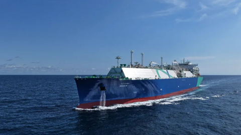
Compared with the onshore LNG receiving terminals, the floating storage and regasification unit (FSRU), as one of offshore receiving terminals, integrates LNG receiving, storage and regasification functions, and has advantages such as low initial investment, short construction period and flexible movement to adapt to market changes.

Compared with the onshore LNG receiving
terminals, the floating storage and regasification unit (FSRU), as one of
offshore receiving terminals, integrates LNG receiving, storage and
regasification functions, and has advantages such as low initial investment,
short construction period and flexible movement to adapt to market changes.
Thus, FSRU has gradually become an important application form of regional gas
supply, seasonal peak shaving or gas supply service in the early stage of
onshore terminal construction. FSRU can be converted from LNG carriers or newly
built, and its storage capacity generally ranges from tens of thousands of
cubic meters to 300,000 cubic meters. It is permanently fixed at the designated
positions through a single-point mooring system or berthed at port/shielded
water jetty position for operation. When the use of FSRU scheme is limited by
factors such as jetty operation water depth and operation sea area, the scheme
of matching floating storage unit (FSU) with floating regasification unit (FRU)
can be adopted to realize FSRU function .
Although LNG carriers can realize the function
of FSU, its application as FSU by mooring at the jetty is different from the
design purpose as a transport ship. Herein, the applicability of LNG carrier as
FSU is evaluated according to the actual situation of layout scheme and the
characteristics of service water area . Aiming at the characteristics of
frequent cargo transfer and continuous unloading in FSU, the risk of layout
scheme and LNG transmission system is also evaluated, and thus appropriate
mitigation measures are put forward, which can provide useful guidance for the
safe operation of LNG carrier as FSU .

Figure 1: Typical Layout of "FSU + FRU" Design
Scheme
1. Technical scheme
Taking the 30,000m3 "M" LNG carrier as an example (see
Table 1 for the main parameters), this project adopts the FSU + FRU design
scheme. The small LNG carrier is moored at the jetty for a long time, functioning
as FSU. Specifically, the shuttle LNG carrier regularly approaches the small LNG
carrier to make up the cargo through ship-to-ship (STS) transfer, and the small
LNG carrier unloads the cargo to the FRU through the jetty boarding ladder and
hose lifting unit. Subsequently, the LNG in the
FRU storage tank is gasified and transported
to the jetty adjustment and control unit, and then the natural gas with
appropriate flow rate, pressure and temperature
is continuously supplied to the onshore power plant or natural gas
pipeline network through the onshore pipeline network .

Figure 2: Mooring Plan I
2. Feasibility analysis
(1) Selection of fender
Fixed arch fenders and four Yokohama movable
fenders have been provided between FSU and jetty, while the equivalent
displacement coefficient C of fenders between FSU and shuttle LNG carrier can
be calculated according to OCIMF equivalent deadweight method, and suitable
fenders can be selected based on its schedule. The scheme is equipped with four
Yokohama movable fenders. If a 22,000m3
LNG carrier is selected as the shuttle LNG carrier, and its maximum
draft is 6m, the berthing collision energy is calculated to be 26.11 tonne·m,
which is less than the maximum absorption energy (68.9 tonne·m) of the selected
fender. The lateral load and tidal load generated by wind are 114.9t and 1.03t,
respectively, which are assumed to be evenly distributed in the four impacts.
The lateral pressure of a single fender is 2.90t/m2 , which is less than the
pressure limit (14.08t/m2) of the fender.
Table 1 Mooring Calculation Results of Plan I


Figure 3: Mooring Plan II
(2) Mooring analysis
As an FSU berthing jetty, the carrier
"M" is moored with 12 cables, including 6 bow cables and 6 stern
cables. The jetty is equipped with a quick cable-removing hook device. The
mooring cables are numbered 1~12 from stern to bow, and the fenders are
numbered A, B, C and D in order. The mooring cable is composed of eight
polyethylene ropes with a diameter of 32mm, a length of 200m and a breaking
limit of 66t. The hydrodynamic analysis software AQWA is used to check the
existing mooring schemes, and the extreme working environment conditions are
selected: wind speed of 15kn, wave height of 0.8m and flow velocity of 3kn. Considering
the normal tidal level = 0m and the high tidal level = 2.7m, the cable tension
is calculated and analyzed in 8 different wind directions (at 45° interval) and
8 working conditions.
Table 2 Mooring Calculation Results of Plan II

From the calculation results, it can be seen
that the cable tension in mooring plan I is within the breaking limit, but the
safety factor is low (less than 1.75), the stress on the fender is uneven, and
the ship moves greatly. Therefore, the scheme is partially optimized to form
plan II, which adopts 6 stern cables and 8 bow cables for mooring. The cables
are numbered 1~14 from stern to bow, and the fenders are numbered A, B, C and D
in order. The calculation and analysis results of AQWA software are shown in
Table 2. The safety factor of each cable in the optimized mooring scheme is
high, and the force on the fender is uniform.
3. Risk assessment
(1) HAZID
As the LNG carrier has its use and nature
changed in case of using as FSU, there are many risks in berthing, mooring,
connection, ship-to-ship transfer, ship-to-shore unloading and other operations
when FSU is fixed at the jetty as a floating storage unit. Therefore, the
hazard sources shall be identified and appropriate control measures shall be
put forward. HAZID analysis is carried out for the carrier "M" as
FSU, which is divided into three nodes:
Node 1: Design scheme of "M" as FSU;
Node 2: Ship-to-ship transmission system
between the shuttle LNG carrier and FSU;
Node 3:
"M" and FRU unloading transmission system 5.
According to the division of the above three
nodes, nearly 20 guide words are selected, and 54 hazard sources are
identified. The existing measures of the design scheme are analyzed, and
suggestions on countermeasures are given.

Figure 4: LNG Pipeline Transmission System
(2) Scenario selection
According to the statistical analysis of LNG
accidents over the years, 75% of the accidents occurred during loading and
unloading operations, and 43% of the accidents were leakage of pipeline joints
and valves. From the above HAZID analysis, it can be seen that the risk level
of LNG leakage during LNG transmission is high, and the harm caused by leakage
at LNG cargo connection manifold on both sides of FSU shall be paid attention
to. Generally, probability analysis of LNG pipeline joint and valve leakage is
needed, and risk value calculation of LNG disaster after leakage is carried out
by combining event tree analysis. In order to simplify the program, four
scenarios, namely, leakage of connection manifold between FSU and Shuttle LNGC,
leakage of LNG to the water surface between two ships, breach of 10% connection
manifold (pipe diameter 250) and 50% connection manifold (pipe diameter 250),
and pipeline pressure of 13bar and 12bar, are directly selected for consequence
simulation analysis.
(3) Consequence simulation
The three-dimensional computational fluid
dynamics (CFD) software FLACS developed by Norwegian consulting company GexCon
is used to calculate the leakage consequences.
Scenario 1: LNG leakage occurs in the
connection manifold between FSU and Shuttle LNGC, with a breach of 10% pipe
diameter and duration of 60s. The calculation results are shown in Figure 7.
After leakage, the LNG diffuses along the length direction, and the maximum
diffusion impact range is 95.86m.
Scenario 2: LNG leakage occurs in the
connection manifold between FSU and Shuttle LNGC, with a breach of 50% pipe
diameter and duration of 60s. After leakage, the LNG diffuses along the length
direction, and the maximum diffusion impact range is 175.82m.

Figure 5: LNG Leakage between FSU and Shuttle LNGC (Breach of
10% Diameter)

Figure 6: LNG Leakage between FSU and Shuttle LNGC (Breach of
50% Diameter)
Scenario 3: LNG leakage occurs in the
connection manifold between FSU and jetty, with a breach of 10% pipe diameter
and duration of 60s. After leakage, the LNG diffuses along the length
direction, and the maximum diffusion impact range is 100.6m.
Scenario 4: LNG leakage occurs in the
connection manifold between FSU and jetty, with a breach of 50% pipe diameter
and duration of 60s. After leakage, the LNG diffuses along the length
direction, and the maximum diffusion sweep range is 147.55m . Any fire source
shall be strictly prohibited in the above four different scenario areas, and
irrelevant personnel shall be prevented from entering.
For LNG plants arranged in open places, because
the possibility of diffusion disaster after LNG leakage is the highest, and the
diffusion impact range is also the largest compared with other disasters of
pool fire, the diffusion concentration range of 2.5% is usually set as the safe
operation distance. Based on the simulation analysis results of disaster
consequences in various scenarios, it is advised that the FSU connection
manifold extend outward within 176m as safety zone.
4. Conclusions and suggestions
As FSU matched with FRU, small LNG carrier can
form a small LNG receiving terminal with FSRU function, which is suitable for
the energy supply scheme of jetty with shallow water depth, small scale and
limited operating conditions. Through the research, the following conclusions
and suggestions are put forward:

Figure 7: LNG Leakage between FSU and Jetty (Breach of 10% Diameter)

Figure 8: LNG Leakage between FSU and Jetty (Breach of 50% Diameter)
(1) The small LNG carrier can berth at the
jetty to provide services as FSU, and its own LNG cargo system can meet the
requirements of LNG receiving, storage and unloading operations, but
compatibility evaluation and confirmation shall be carried out according to the
actual situation on site;
(2) Due to the limitation of jetty
infrastructure, frequent ship- to-ship transfer, continuous ship-to-shore
operation and long-term berthing, some additional risks will be brought to FSU.
Thus, FSU berthing and mooring, hose connection, operation procedures and
safety management shall be considered emphatically;
(3) When FSU is berthed at the jetty for
operation, the operation safety area shall be determined by QRA method, and
eye-catching signs shall be set. Irrelevant ships and personnel are strictly
prohibited from entering the safety zone.
Note: If you need to reprint, please indicate the source of the information.