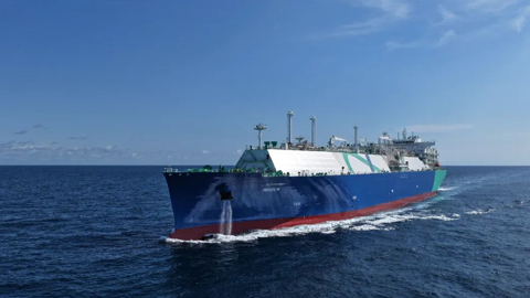
With the acceleration of decarbonization in the global shipping industry, ammonia, as a highly-anticipated green energy star, is gradually becoming a key driving force for the transformation and upgrading of the shipping industry by virtue of its environmental characteristics of near-zero carbon emissions and cost advantages.
By Feng Yuxiang, CCS Wuhan Rules & Research
Institute
Liu Shaoling, COSCO Shipping Heavy Industry
(Dalian) Co., Ltd.

With the acceleration of decarbonization
in the global shipping industry, ammonia, as a highly-anticipated green energy
star, is gradually becoming a key driving force for the transformation and
upgrading of the shipping industry by virtue of its environmental
characteristics of near-zero carbon emissions and cost advantages. According to
the relevant requirements of the CCS "Guidelines for Ships Using Ammonia
Fuel", "the purpose of risk assessment is to ensure that necessary
assessment is made on potential risks involving ammonia fuel, so as to
eliminate or mitigate the adverse effects on personnel, environment, structural
strength, or ship integrity. At this point, in order to guarantee the intrinsic
safety and system safety of ammonia-fuelled vessels and optimize their
operating procedures, this paper takes the design scheme of an ammonia-fuelled
harbor workboat under construction as an example to conduct risk assessment on
its system arrangement and process design scheme based on hazard identification
(HAZID), hazard and operability analysis (HAZOP), as well as consequence
quantitative analysis method, etc.
Case Overview
By taking the ammonia-fuelled system
design scheme of a certain ammonia-fuelled harbor workboat as the analysis
object, HAZID/HAZOP analysis is carried out based on the design drawing of the
ship. The main parameters of the ship are shown in Table 1.

Table 1 Main Parameters of the
Ammonia-fuelled Harbor Workboat Under Construction
The ammonia fuel is stored in a
fully-pressurized liquid state at a storage pressure of about 1.6 MPa (working
pressure) and a working temperature of -20 ℃~40 ℃. The ammonia
fuel tank is arranged on both sides behind the main deck engine room casing, is
equipped with injection, discharge, pressure release and other interfaces as
required, and is provided with the functions of local monitoring of liquid
level, pressure and temperature, as well as remote monitoring of pressure and
temperature. For the convenience of handling of leaks at the joints of the fuel
tank, a liquid collection tray is installed below all possible leakage points
including joints, valves, etc. Each ammonia fuel tank is equipped with 2 sets
of pressure relief valves (PRVs) with two interlocked isolation shut-off
valves.
The gaseous ammonia fuel is allowed to
enter the main engine, with a pressure of about 0.5~1.0MPa and a temperature of
20 ℃~40 ℃. The fuel supply system mainly consists of a pressure
reducing valve set, an evaporator, and a buffer tank. The buffer tank needs to
be insulated with a working pressure of 0.5-1.6 MPa. The heat source of the
evaporator comes from the jacket water of the main engine, and a tubular heat
exchanger is used. The pipelines for ammonia and jacket water are respectively
introduced to the intermediate heat exchange medium to achieve heat exchange.
HAZID Analysis
1.
Node Division
For the convenience of HAZID analysis,
the ammonia fuel power system equipment and arrangement of the ship are divided
into five nodes for further analysis, namely: ① ammonia bunkering station (including filling joints,
liquid phase pipelines, gas phase pipelines, control valves and accessories,
etc.); ② ammonia fuel tank (fuel tank, related
accessories, etc.); ③ ammonia fuel preparation room (pumps,
heat exchangers, buffer tanks, etc.); ④ ammonia fuel engine compartment (main engine,
post-treatment device); ⑤ ammonia release cabinet (sewage storage
tank).
2.
HAZID Analysis Table
Based on the HAZID method, the causes,
consequences, existing protective measures, risk levels, and recommendations
for the hazards caused by the design layout of each node, process flow,
equipment fault, human operation, etc. are analyzed regarding the equipment,
process system, and layout of the ammonia-fuelled system of the ship. The HAZID
analysis table (excerpted nodes of ammonia fuel bunkering station) is shown in
Table 2.

Table 2 HAZID Analysis Table of the
Ammonia-fuelled Harbor Workboat (Excerpted Nodes of Ammonia Fuel Bunkering
Station)
HAZOP Analysis
1. Nodes Division
For the convenience of HAZOP analysis,
the power system process of the ship is divided into several nodes for further
analysis. According to the working principle, it can be divided into the
following nodes: ① liquid ammonia bunkering (ammonia fuel
from the bunkering station to the fuel tank); ② BOG return gas (BOG from ammonia fuel tank to tank
bunkering truck); ③ ammonia supply (ammonia in the fuel
tank to the heat exchanger through its own pressure); ④ liquid ammonia supply (liquid ammonia
in the fuel tank is pressurized by the pump group and then sent to the heat
exchanger); ⑤ ammonia fuel gas (ammonia fuel passes
through the heat exchanger to a buffer tank and then to the gas equipment); ⑥ blowing and ventilation (blowing and
ventilation pipeline to ammonia release cabinet).
2. HAZOP Analysis Table
Based on the HAZOP method, the causes,
consequences, existing protective measures, risk levels, and recommendations
for the hazards caused by equipment fault, human operation, etc. at each node,
are analyzed regarding the ammonia bunkering system, ammonia supply system,
etc. of the ship. The HAZOP analysis table---excerpted nodes of liquid ammonia
supply (the liquid ammonia in fuel tank is pressurized by the pump group and
then sent to the heat exchanger) is shown in Table 3.
Consequence
Analysis of Leakage
Based on the above qualitative risk
assessment results, combined with the technical conditions and functional
characteristics of the ammonia-fuelled harbor workboat, it has been determined
that ammonia fuel leakage in the fuel preparation room during ship operation
and ammonia fuel leakage at the bunkering station during ship bunkering are
high-risk scenarios. Quantitative calculation and risk assessment are conducted
for the two high-risk scenarios.
This analysis will be conducted by using
the computational fluid dynamics (CFD) software FLACS, which was developed with
the funding and guidance from oil companies including BP, Conocophillips,
ExxonMobil, Statoil, and three national legislative bodies including the Health
and Safety Executive (HSE) of the UK, the Norwegian Petroleum Directorate
(NPD), and the German Federal Ministry for Research and Technology (BMFT).
FLACS is an explosion hazard assessment tool designated by major international
oil and gas companies, which can meet the risk assessment requirements of
relevant international standards in the oil and gas industry (such as ISO13702,
NORSOKZ-013, ISO/DIS 19901-3, etc.).

Table 3 HAZOP Analysis Table — Excerpted
Nodes of Liquid Ammonia Supply (the liquid ammonia in fuel tank is pressurized
by the pump set and then sent to the heat exchanger) for the Ammonia-fuelled
Harbor Workboat
Analysis is made by taking the scenario
of small aperture liquid ammonia leakage at the flange connection of the
ammonia fuel bunkering station during the bunkering operation as an example,
with 50% of the ammonia explosion bottom line as the boundary. The diffusion
range of combustible gases is shown in Fig. 1, and the diffusion range of toxic
gases is shown in Fig. 2.

Fig. 1 Diffusion Range of Combustible
Gases (8%~28%)

Fig. 2 Diffusion Range of Ammonia with a
Concentration of300ppm After Leakage of the Bunkering Liquid Phase Flange
It can be seen that when there is
leakage in the bunkering joint, a liquid pool is first formed in the liquid
collection tray after the liquid ammonia leaks, with massive gasification into
low-temperature heavy gas containing a small amount of liquid ammonia droplets.
The combustible vapor range of the gas is mainly located in the liquid
collection tray and adjacent lower areas, and is basically covered by the
dangerous areas of the ship. The threshold for toxic vapors is based on the
Chinese national occupational health standard GBZ2.1, IDLH (NH3)=300ppm, so the
upper limit of the threshold is taken as 300ppm. In addition, the toxic vapor range
covers some sensitive air inlets of the ship (such as the stern rudder engine
room air inlet), and the maximum toxic gas diffusion range is about 133m in the
length direction and 73m in the width direction of the ship.
Risk Assessment
Conclusion and Recommendations
Based on the system design scheme of the
ammonia-fuelled harbor workboat under construction, the following conclusions
and recommendations are provided based on our risk assessment:
1. Through HAZID analysis of 5 nodes and
HAZOP analysis of 6 nodes, a total of 23 low-risk scenarios, 30 medium risk
scenarios, and 4 high-risk scenarios are determined through assessment. Among
them, the high-risk scenarios include damage and leakage at the ammonia fuel
bunkering station and liquid ammonia leakage in the fuel preparation room. The
main risk control measures are as follows: ① in case of damage/leakage at the ammonia fuel bunkering
station, it is recommended that qualified professional operators should operate
and wear PPE, during the bunkering operation, the bunkering personnel should
carry portable ammonia vapor detectors; adjust the position of the disinfection
spray head and eye washing facilities; in the case of significant bunkering
temperature difference between the two parties, implement the measures such as
verifying whether the bunkering pressure difference can be established, and
reduce its risk level to an acceptable extent; ② for fuel preparation room leakage, it is recommended to
implement such measures as setting up water sprays inside the fuel preparation
room, triggering a leakage alarm, collecting sewage and discharging it into the
sewage tank, etc. to reduce the risk level to an acceptable extent.
2. Through further diffusion analysis of
the consequences of the leakage, the results show that when leakage occurs at
the bunkering station, the toxic gas may have a large impact range. It is
recommended to divide the restricted operation areas according to the
quantitative calculation results, and strictly control the entry of
non-bunkering personnel within the restricted areas. The bunkering personnel
should wear PPE and portable ammonia vapor detectors. At the same time,
bunkering operations should be arranged according to the wind direction during
on-site operations, and be carried out as much as possible when the wind
direction is opposite to the bunkering dock. For the steering engine room inlet
at the stern of the ship, the safe area air inlet at the bow of the ship, and
the opening of the cab facing the bunkering station and the side of the ship,
the diffusion range of toxic ammonia gas may cover the above positions in case
of leakage. It is recommended that the above air inlets and openings be
designed as closed types, and toxic gas detectors should be installed at the
inlet and interlocked with the above air inlets and openings.
Note: If you need to reprint, please indicate the source of the information.